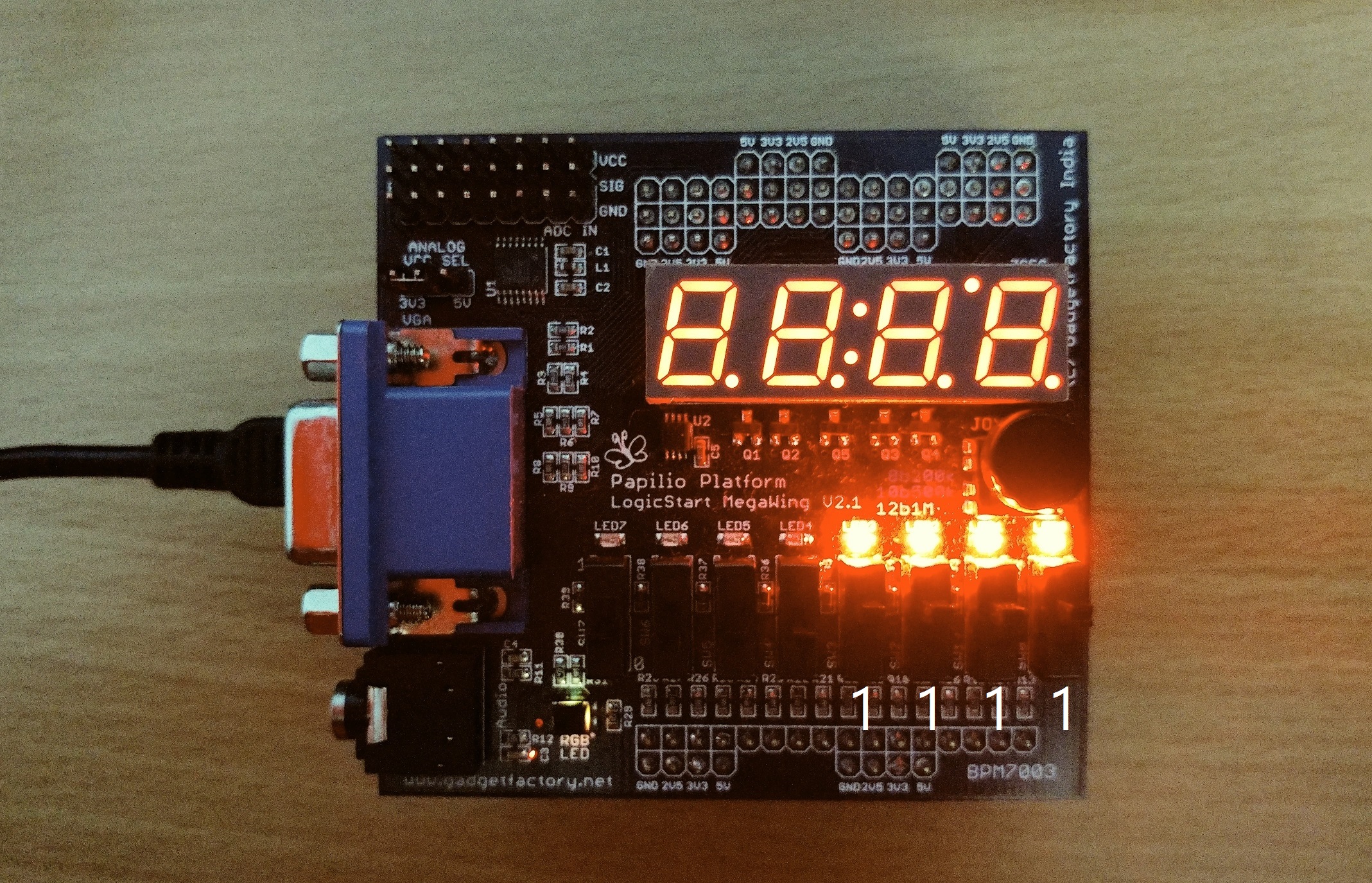
Xilinx provides its own softcore processor IP Microblaze to use in embedded systems application. In this post and a few that follow up, I will implement the Microblaze softcore processor on Spartan 3E FPGA. After that’s done I will use Xilinx provided SDK(Software Development Kit) to write a C program to turn on LEDs using switches.
The whole step involved in setting up Microblaze system is somewhat lengthy but simple.
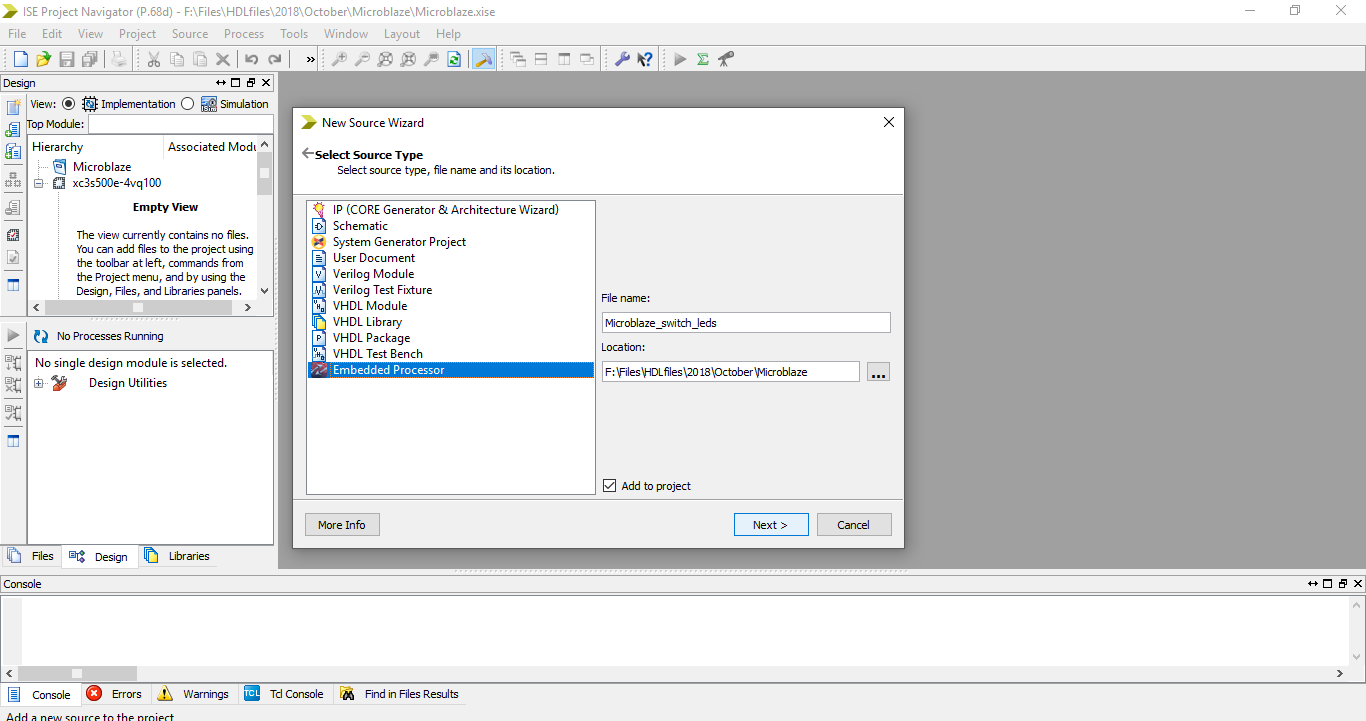
Step 1: Create a new project and select Embedded Processsor from the new source wizard. Enter file name and click next.
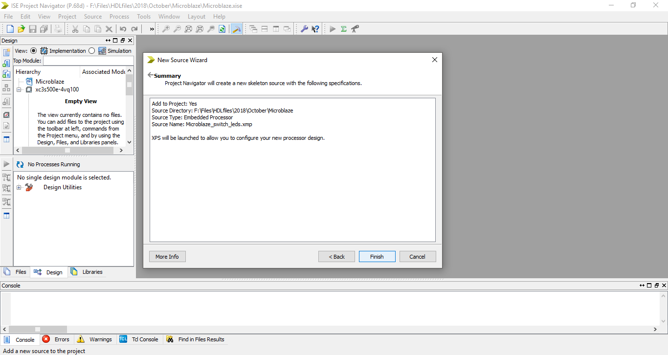
Step 2: On the next window it shows the summary of the file created and says XPS will be launched. Click finish
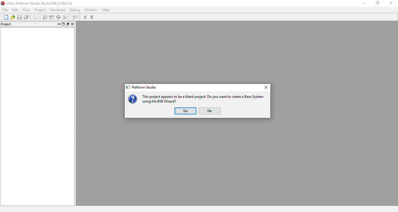
Step 3: Xilinx Platform Studio will open up asking if you want to create a Base System using the BSB Wizard. Select yes.
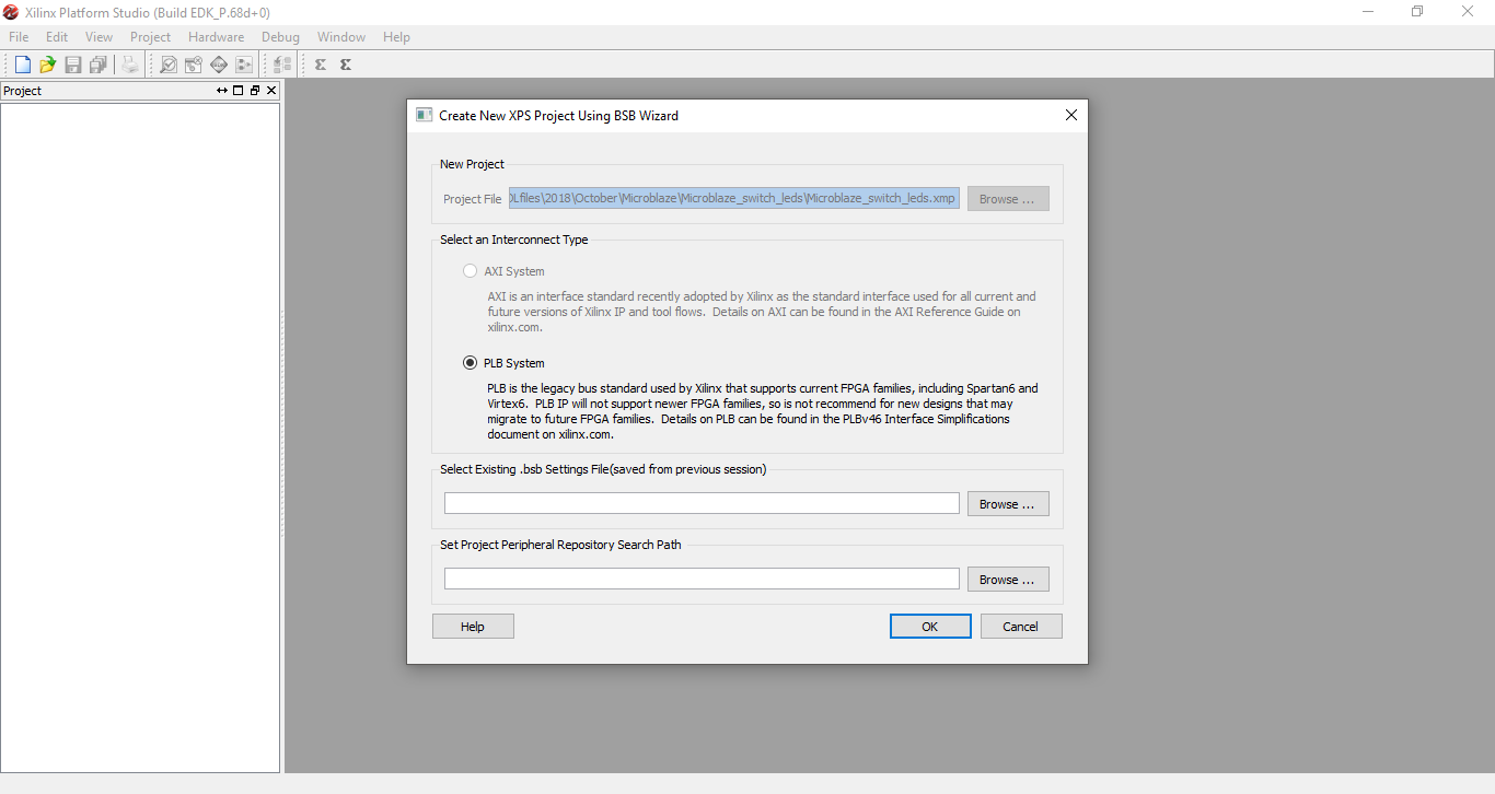
Step 4: On the Create New XPS Project window select the type of the Interconnect and click ok. In case of Spartan 3E FPGA, AXI interconnect system is not present so PLB system is selected as default.
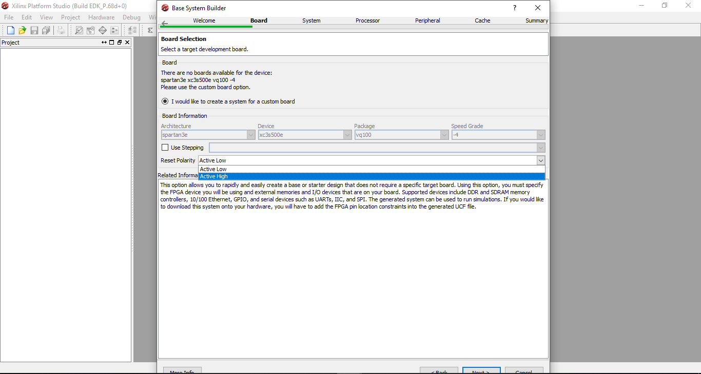
Step 5: On the Base System Builder window selct the option to create a new design and click next.

Step 6: Select the Reset Polartiy as Active Low or Active High and click next. I selected Active High for this example.
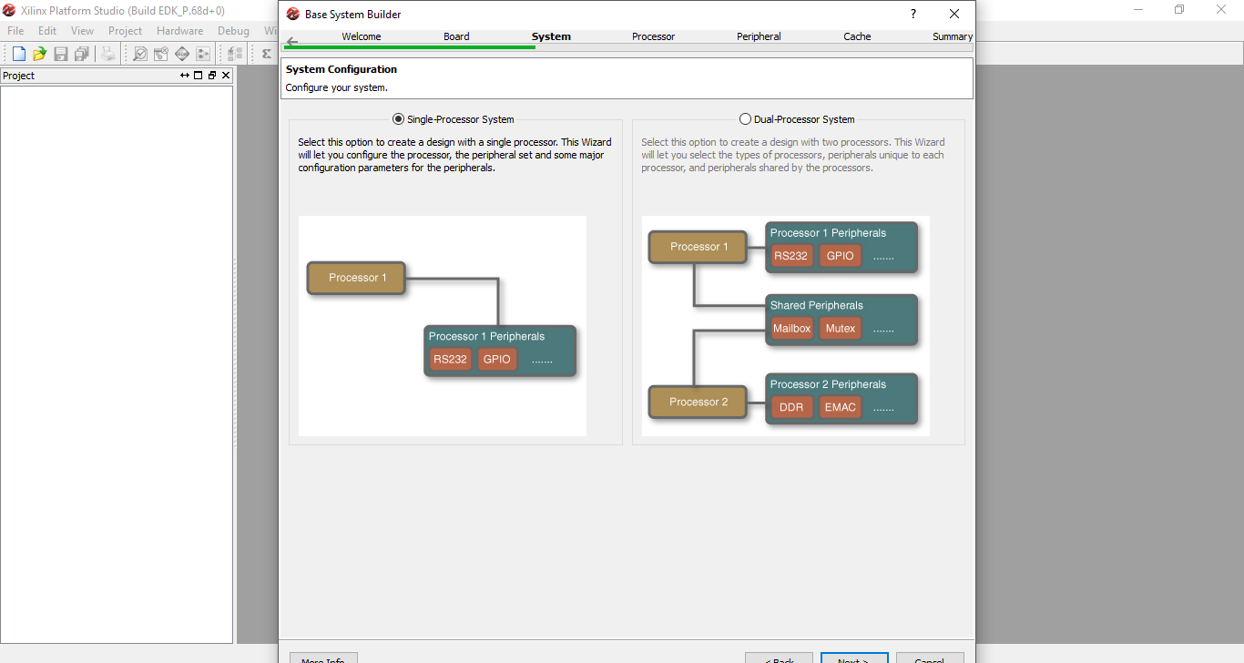
Step 7: On the System Configuration section, select the Single-Processor System and click next. Single-Processor System is easy to work with and is more than enough for this example.
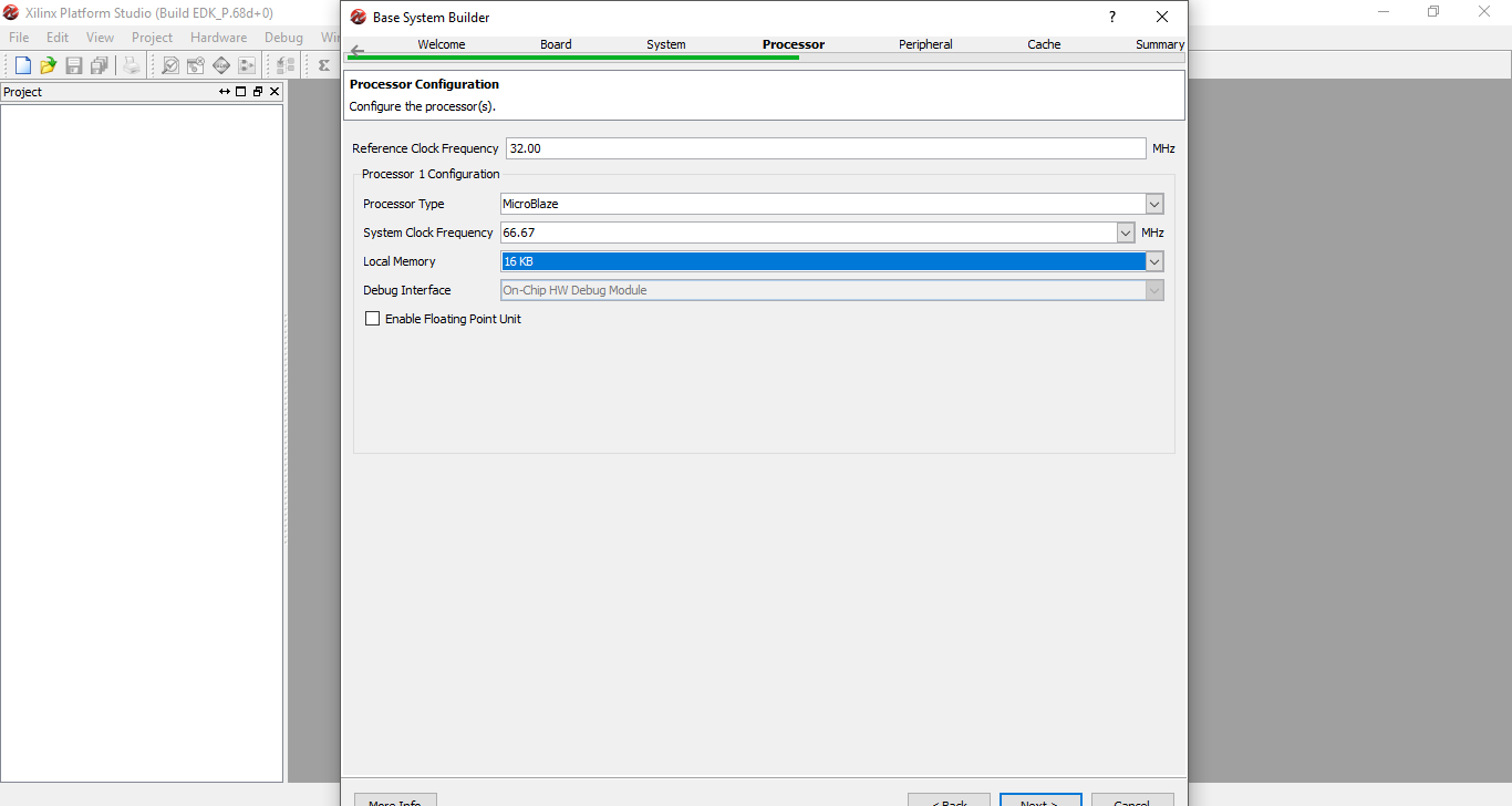
Step 8: On the next window enter the Reference Clock Frequency same as FPGA board clock frequency. Select Local Memory as required and click next. In case of Papilio One the frequency is 32 MHz.
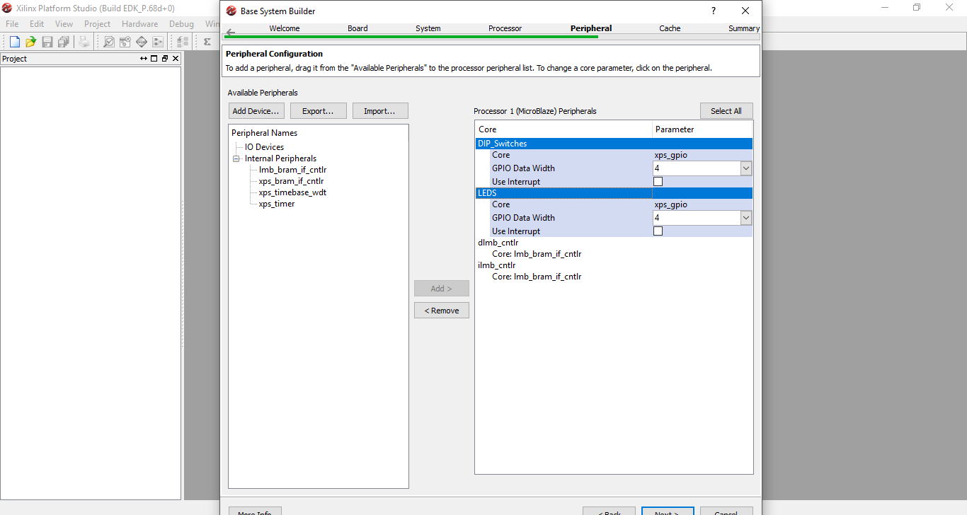
Step 9: On the Peripheral section add the two GPIO devices DIP_Switches and LEDS. Select GPIO Data Width as 4 for both the devices and click next.
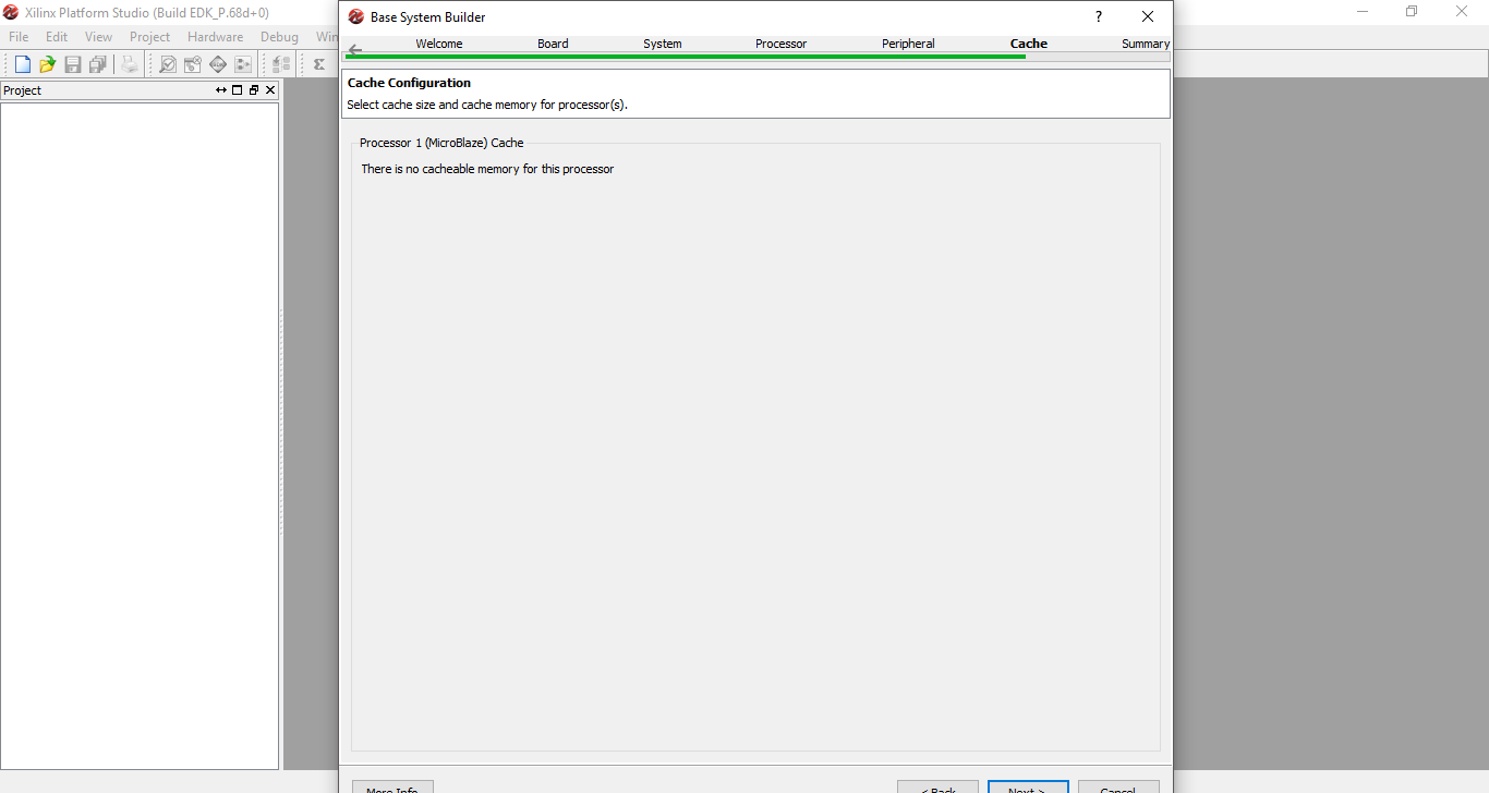
Step 10: On the Cache section it says no cacheable memory for the processor because I didn’t add any cache memory. Click next.
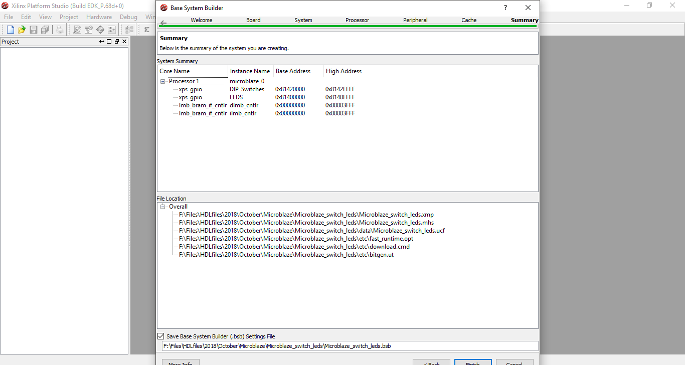
Step 11: Check the summary and see if the added devices are shown. Click finish
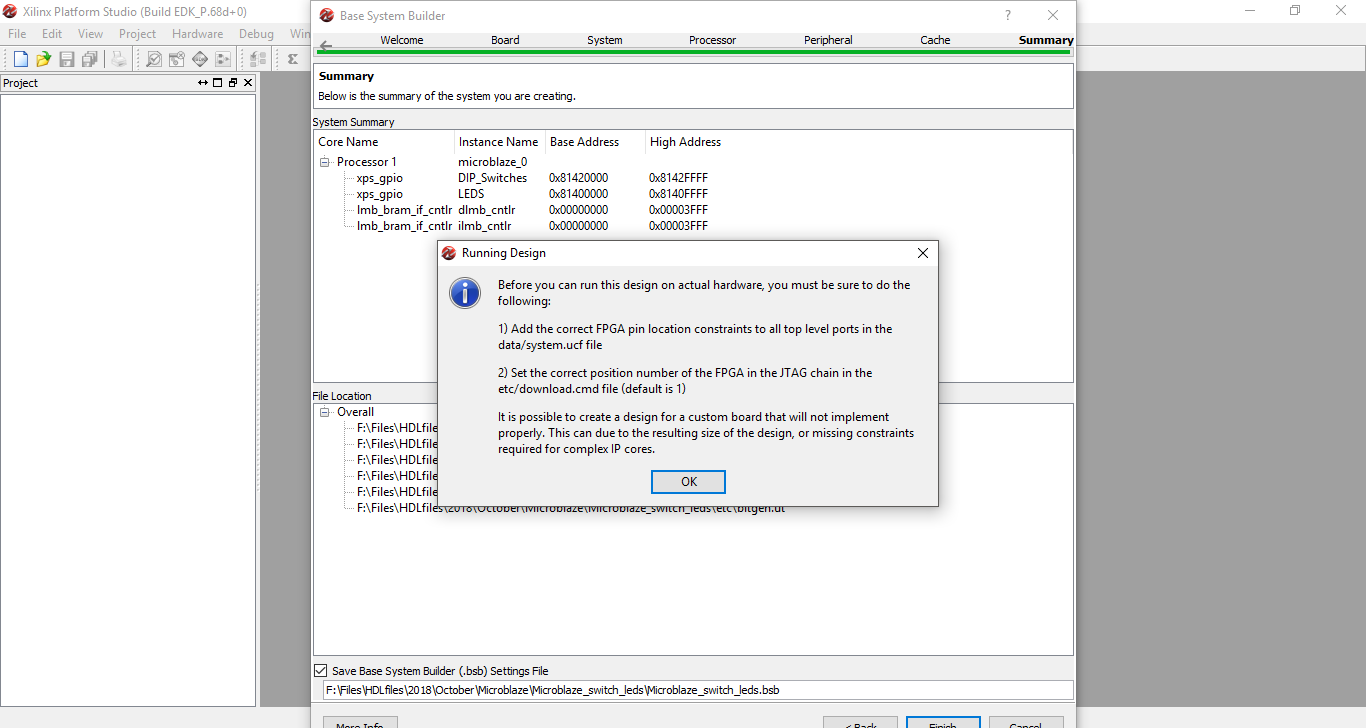
Step 12: A Running Design window will pop up. Select ok
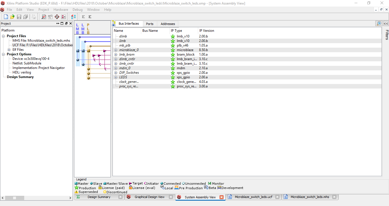
Step 13: Now the Xilinx Platform Studio will open up with the configured processor system. Check for added devices in Bus Interfaces, Ports and Addresses window. Click on UCF File on the right side under Project Files.
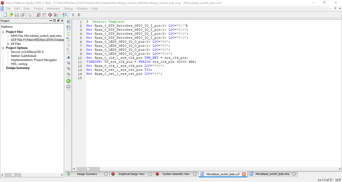
Step 14: Add the pin locations of the switches, leds, reset and clock.
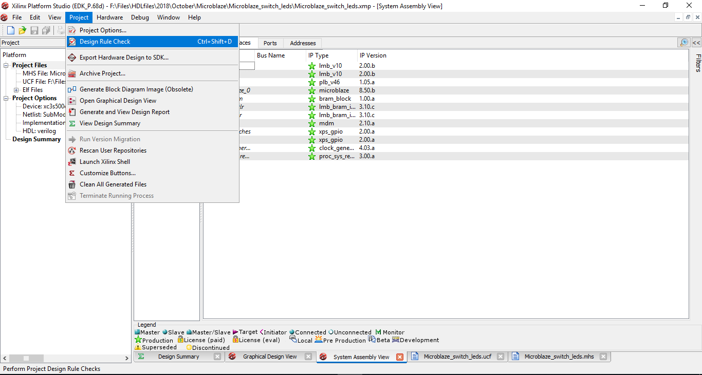
Step 15: After all the pin constraints are added click on the Project menu and select Design Rule Check.
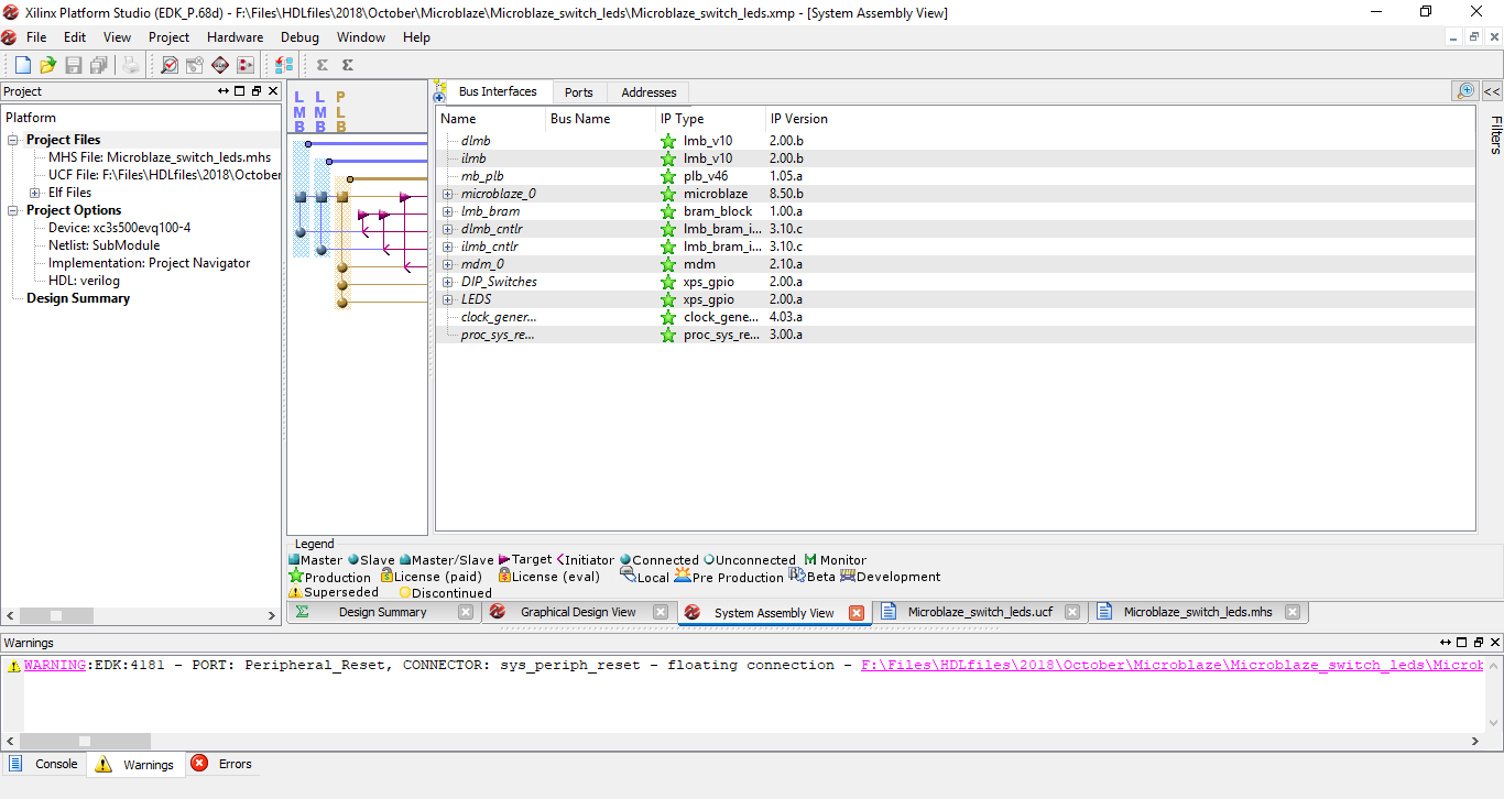
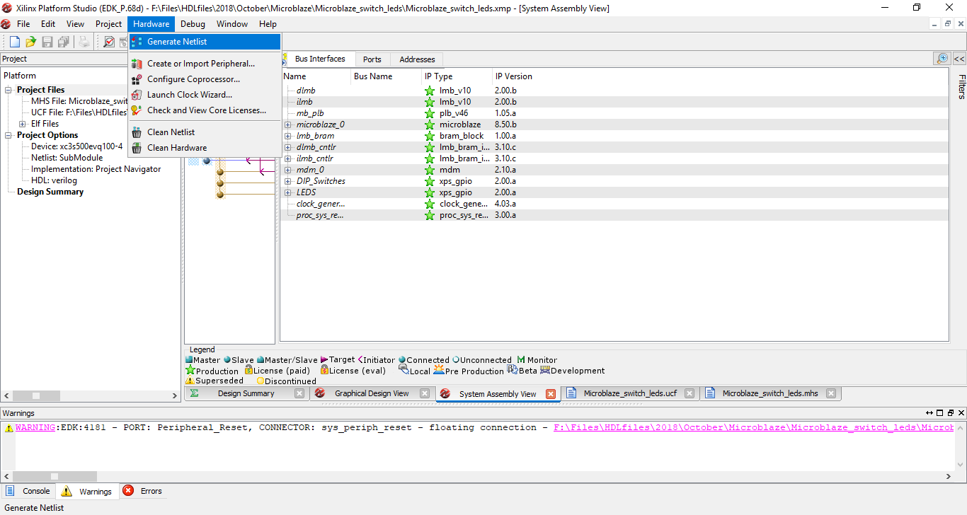
Step 16: After design rule check is completed it will show a warning saying floating connection. It doesn’t cause any issue in the final implementation.
Step 17: On the Hardware menu double click on Generate Netlist. This will take around 20-30 mins to complete.
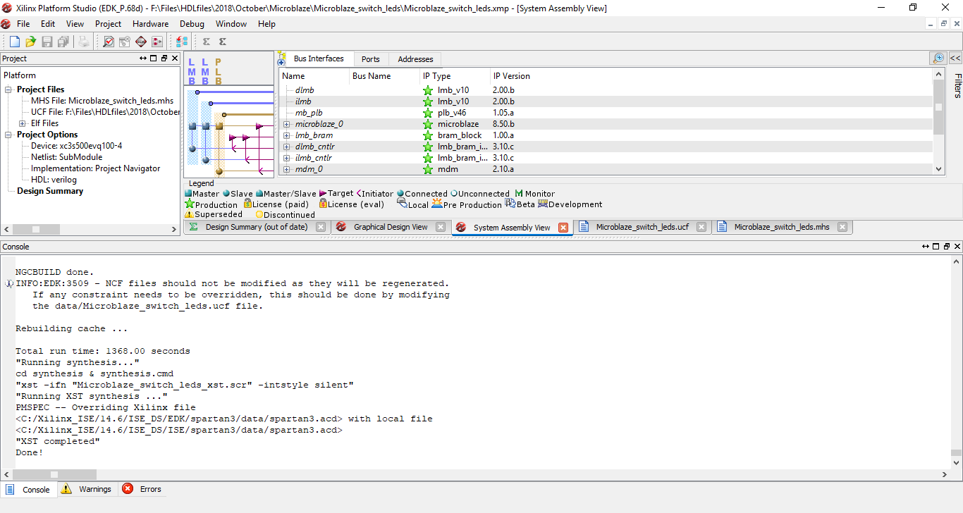
Step 18: After the process is complete on the console window it says “XST completed” Done!. Close the Platform Studio and go back to Project Navigator.
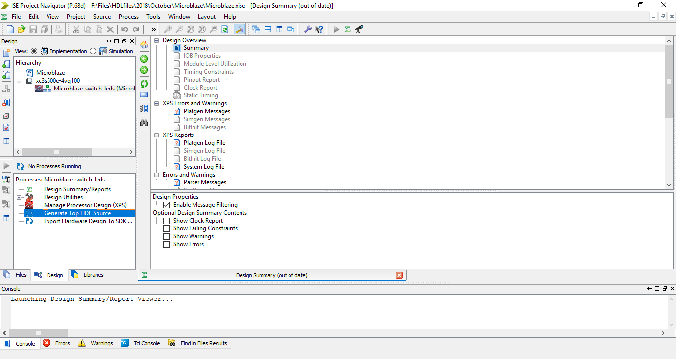
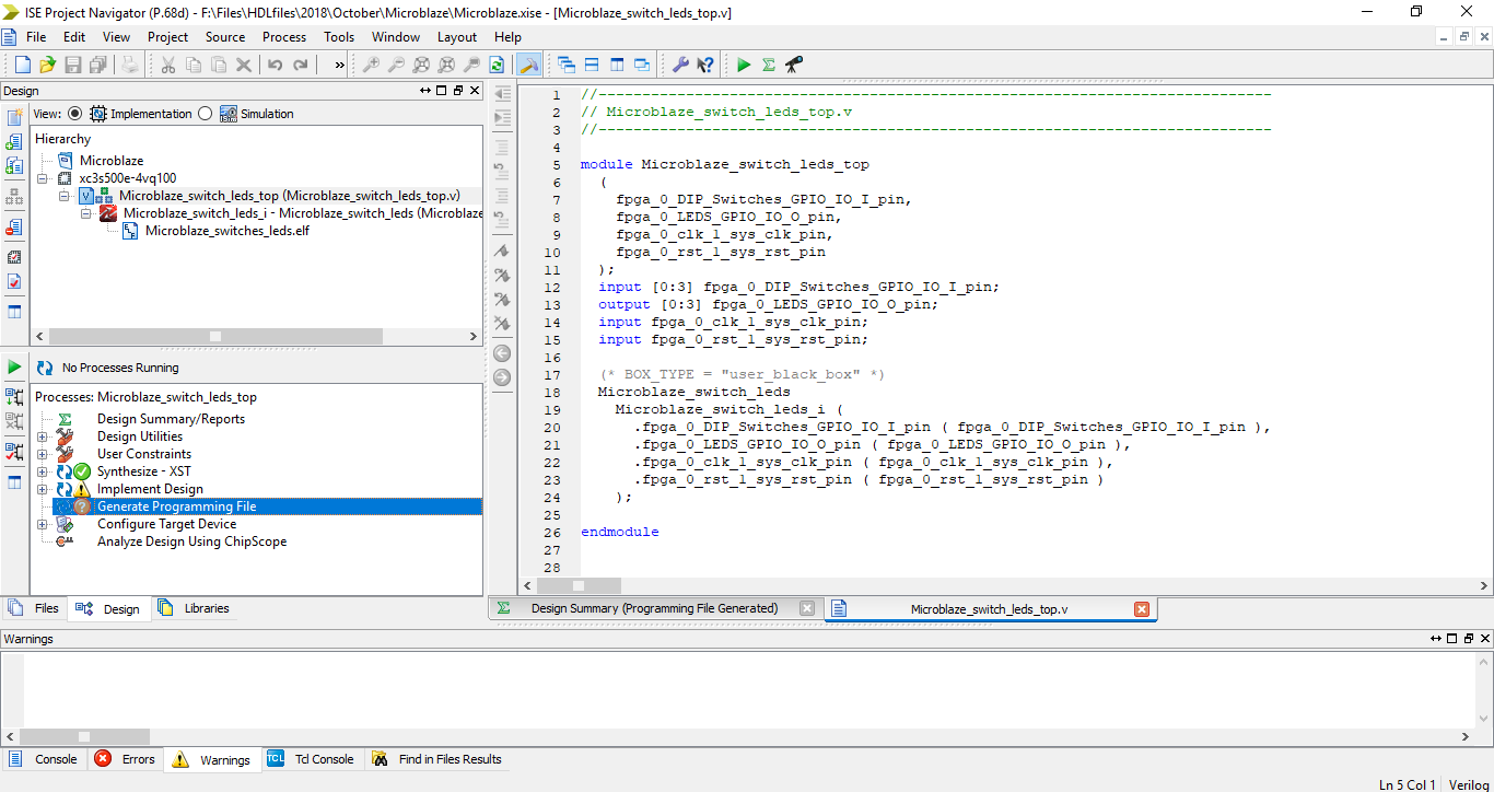
Step 19: On the Processes window double click on Generate Top HDL Source.
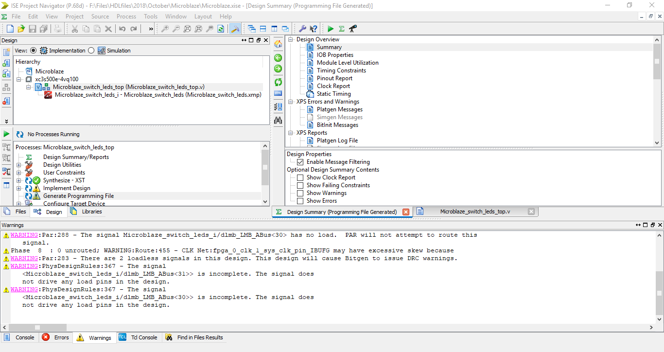
Step 20: Select the top module and double click on Generate Programming File. Ater that’s done it will show a few warnings related to JTAG pins not connected.
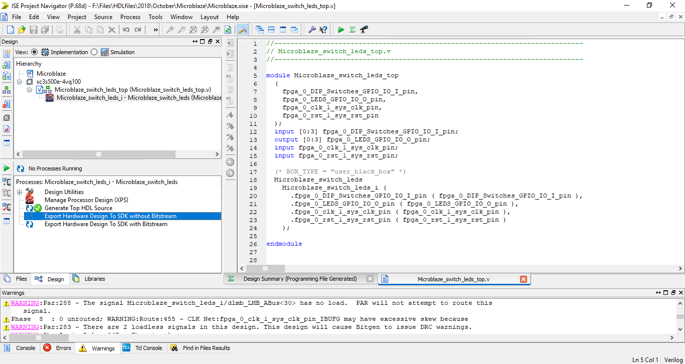
Step 21: Select the Microblaze System .xmp file and under processes tab double click on Export Hardware Design To SDK without Bitstream. This will open up the Software Design Kit where you can write a program in high level language for the processor.
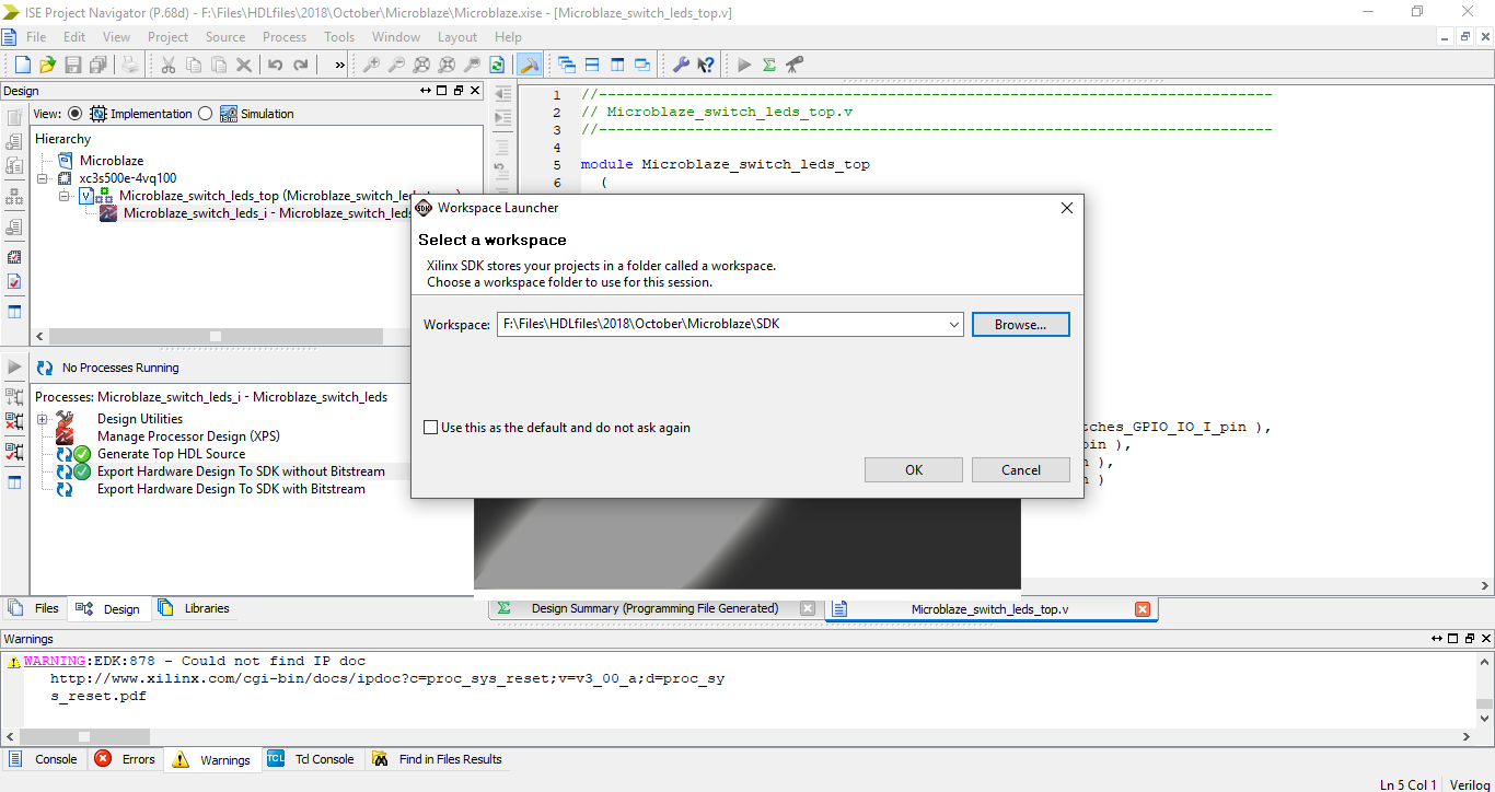
Step 22: Select a workplace destination and click ok.
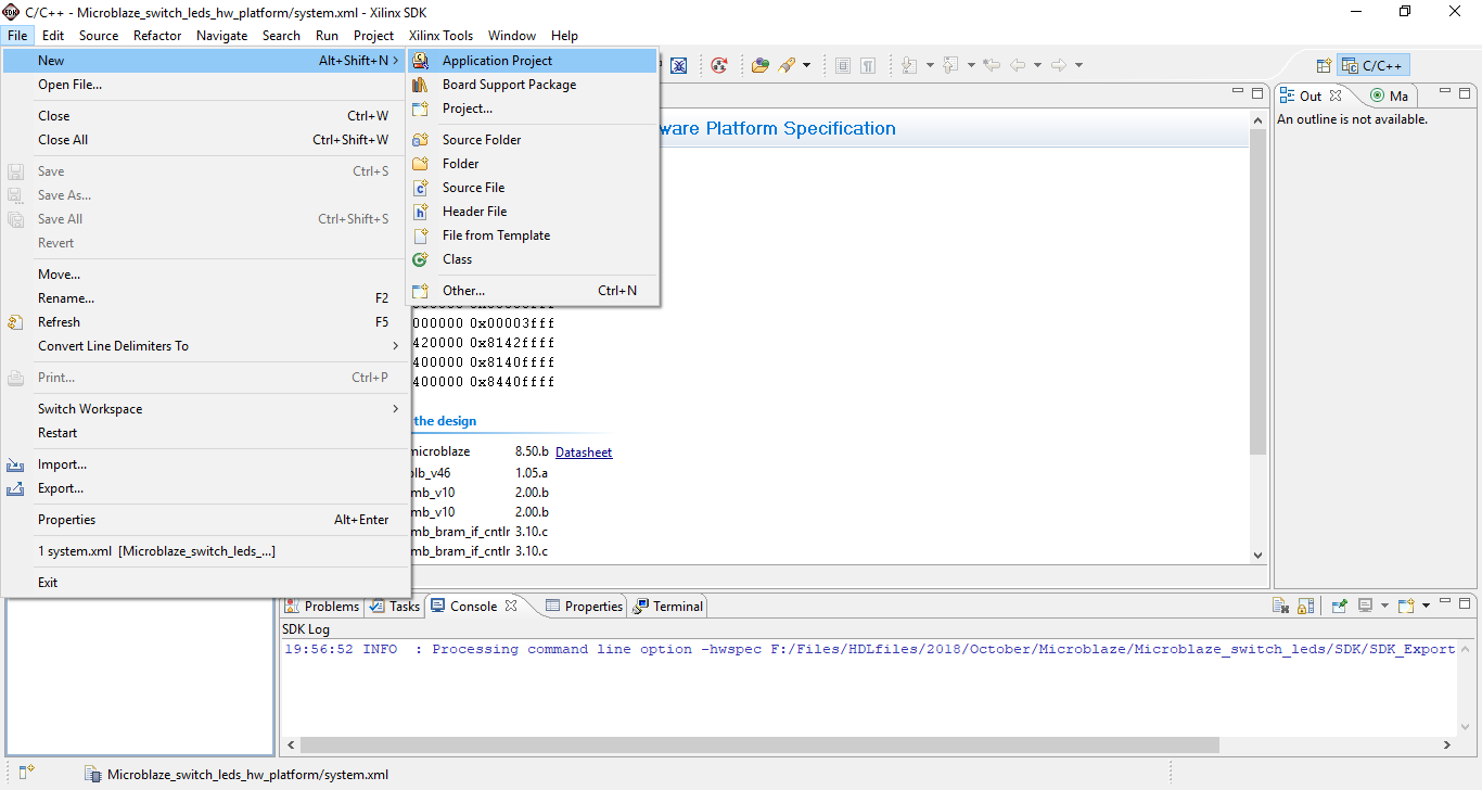
Step 23: On the File menu click on New -> Application Project.
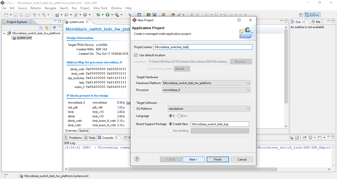
Step 24: Type the Project name and choose the required language. In this case I chose C and on the next window select example type as hello world. Click Finish
Step 25: Navigate the project created earlier and under src select helloworld.c and rename it to Switch_led.c.
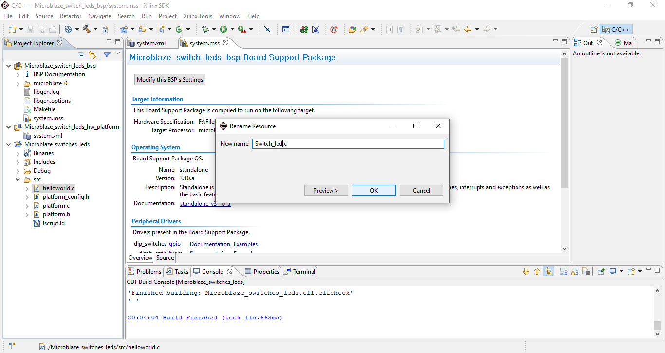
Double click on the renamed .c file and replace the default program with the below program.
1
2
3
4
5
6
7
8
9
10
11
12
13
14
15
16
17
18
19
20
21
22
23
24
25
26
27
28
29
30
31
32
33
34
35
36
37
38
39
40
41
42
43
44
45
46
47
48
49
50
51
52
53
54
55
56
57
/***************************** Include Files *********************************/
#include <stdio.h>
#include "xparameters.h"
#include "xgpio.h"
#include "platform.h"

/************************** Variable Defintions ******************************/

XGpio Gpio_leds;  //Gpio_leds is user defined variable
XGpio Gpio_keys;  //Also same as above

int main()
{
	 int Status;
	 int i;
	 u32 Delay;
	 u32 DataRead;

	 init_platform();

	 Status = XGpio_Initialize(&Gpio_keys, XPAR_DIP_SWITCHES_DEVICE_ID);
	 if (Status != XST_SUCCESS) {
		  return XST_FAILURE;
	 }

	 XGpio_SetDataDirection(&Gpio_keys, 1, 0xFFFFFFFF);    //set Gpio_keys is input

	 Status = XGpio_Initialize(&Gpio_leds, XPAR_LEDS_DEVICE_ID);
	 if (Status != XST_SUCCESS) {
		  return XST_FAILURE;
	 }

	 XGpio_SetDataDirection(&Gpio_leds, 1, 0x0);         //set Gpio_leds is output

 while(1)
  {
	 DataRead = XGpio_DiscreteRead(&Gpio_keys, 1);

	 if((DataRead & 0x0f)!=0x0f){                      //if key is pushed
		for (Delay = 0; Delay < 2000; Delay++);
		DataRead = XGpio_DiscreteRead(&Gpio_keys, 1);  //read again
	 	if((DataRead & 0x0f)!=0x0f)
	 	{
 	 	      XGpio_DiscreteWrite(&Gpio_leds, 1, DataRead);
	 	}
	 }
	 else{                                             //if key is not pushed
			for (Delay = 0; Delay < 2000; Delay++);
			DataRead = XGpio_DiscreteRead(&Gpio_keys, 1);  //read again
		 	if((DataRead & 0x0f)==0x0f)
		 	{
	 	 	      XGpio_DiscreteWrite(&Gpio_leds, 1, DataRead);
		 	}
	 }
  }
    return 0;
}
Save the program file. This will automatically compile the program and after the compilation is done close SDK and go back to Project Navigator.
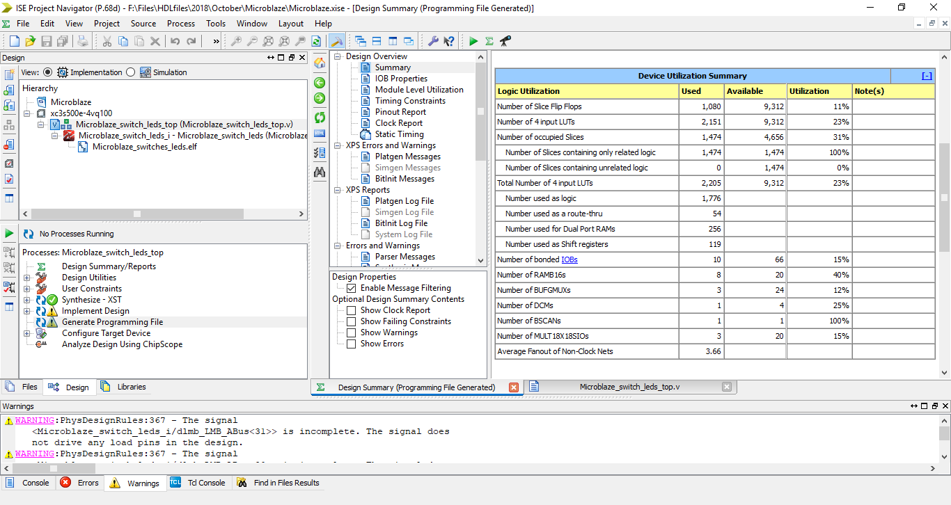
Step 26: Right click on the Hierarchy tab and select add source. Locate the .elf file from the SDK workplace -> debug folder and add it to the project. After the .elf file is added double click on Generate Programming File.
Step 27: Once the process is completed view the Device Utilization Summary and note the resources used.
Locate the bit file and upload it to the FPGA board.