The goal of this project is to design an I²C core in verilog, implement it on FPGA and interface it with I²C sensor LM75A to read the temperature data. The main part of this project is to design an I²C controller which is quite easy to do once you understand the protocol. But this project wouldn’t be possible without a good documentation of LM75A. Thanks to NXP for this excellent datasheet. LM75A is a digital temperature sensor and thermal watchdog, since the I²C controller has to read data from LM75A, knowing which register to access, what bits to consider is essential here and it is explained very well in the datasheet.
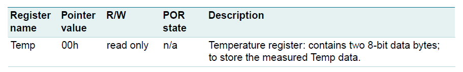
LM75A has four registers, but the register of our interest is the temperature register which stores two byte of information. Each register has a pointer value and it is 00h for temperature register. During power up the pointer value is already at 0, so we need not specify the pointer value to read the temperature.
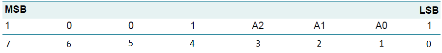
The address which is to be sent is shown above. Here 0th bit indicates read/write operation. As we are reading from the sensor, it should be 1. Bits 1 to 3 specifies the slave address. It is taken as 000 since we have only one slave. Bit 4 to 7 is preset to 1001 by hard-wiring inside the LM75A.
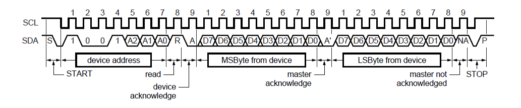
That’s all about LM75A we need to know just for reading the temperature. Now the next task is to design I²C module as per the protocol, which is explained very well over here. The Sparkfun tutorial shows only one byte of data to be read or written. But, the LM75A temperature register stores two byte of data. Hence the read data cycle has to be carried out twice.
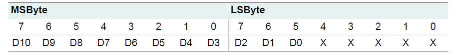
In the two bytes of data received from LM75A, the bits 0 to 4 should be ignored because the interal circuitry of the LM75A is such that those 5 bits are zero. So only 11 bits are considered.
Output:
This 11-bit binary number should be multiplied with 0.125 to get the temperature in degree celsius. If D10=0, the temperature is positive. If D11=1, the temperature data should be 2’s complimented and multiplied with 0.125 to get negative temperaure in °C.
Simulation output:
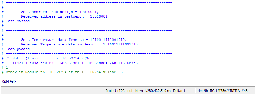
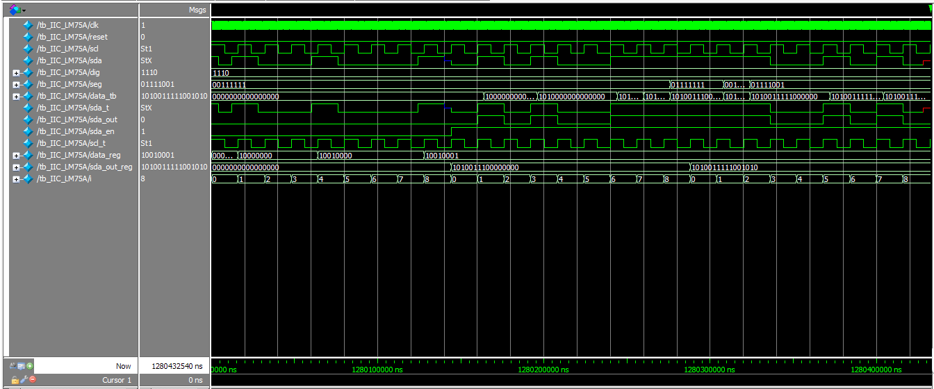
Simulation waveform:
Hardware setup
Implemented on Papilio One FPGA board
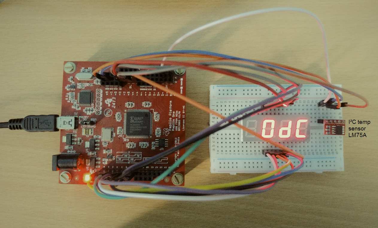
The 11-bit output is converted to hexadecimal and indicated on the seven segment display. Output: (dc)₁₆ * 0.125 = (220)₁₀ * 0.125 = 27.5°C