The goal of this project is to:
- Design UART receiver and transmitter in SystemVerilog.
- Test the design in UVM and SystemVerilog based testbench environment.
- Synthesize the design and implement it on Cyclone IV FPGA board.
- Interface the board with PC using hyperterminal.
Here’s a brief overview of this project:
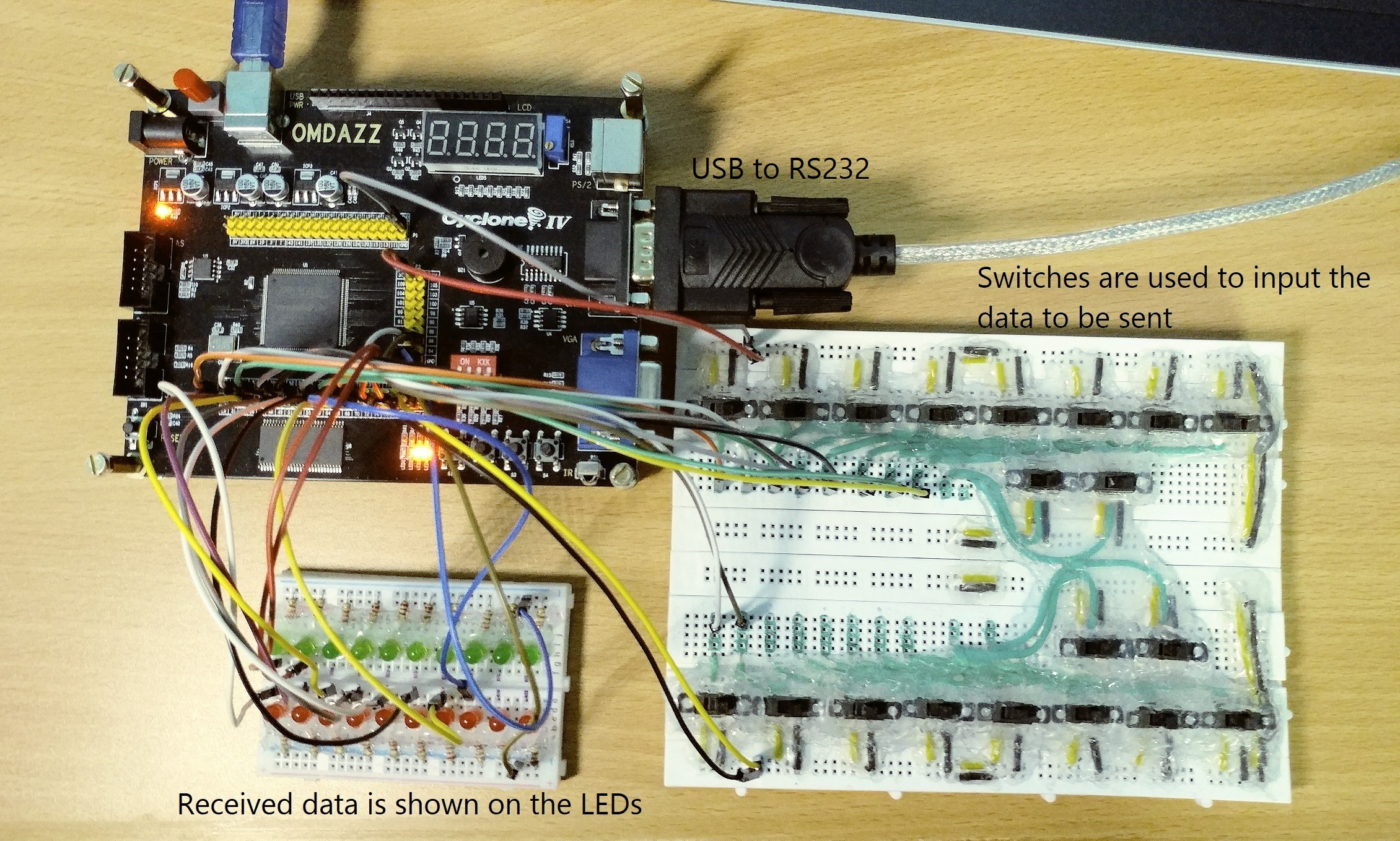
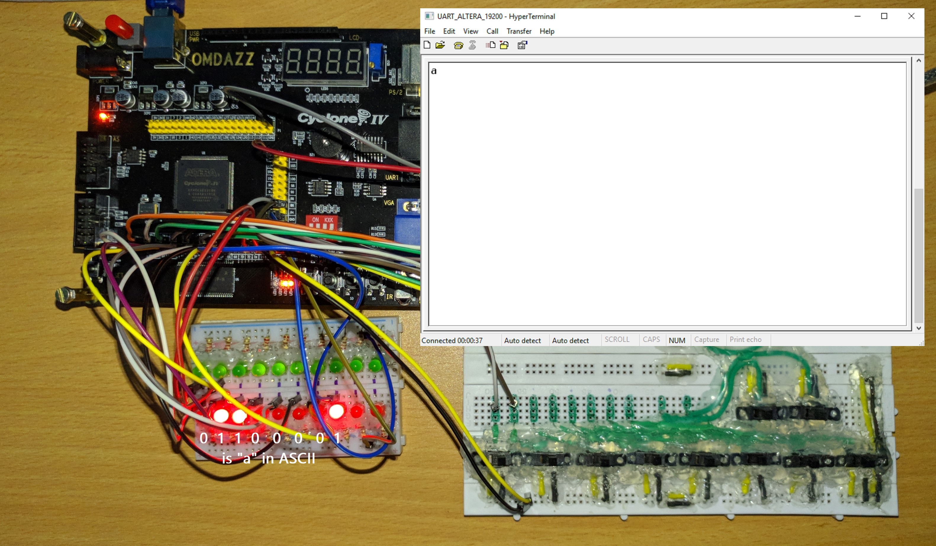
The main part of this project is the UART itself which is coded in SystemVerilog. I have developed receiver and transmitter as seperate modules. Both the modules are instantiated in the top module through which all the interface takes place. The design is verified using UVM and SV. After the design works in simulation, it is synthesized using Altera Quartus II to generate the bitstream for the FPGA. The FPGA board is interfaced with PC at a baud rate of 19200 using hyperterminal software and to and fro communication between PC and FPGA is verified. I have used switches to give input to the PC which is indicated as ASCII character on the screen. The input from keyboard is indicated on the LEDs.
UART Protcol:

- In UART the data transmission and receiving takes place without a common clock between the two devices. Hence the two devices must work at the same speed called baud rate. In this project the baud rate of the UART is considered to be 19200. Using baud rate and FPGA clock frequency, the clock per bit is calculated: clock per bit = (clock frequency/baud rate)
For Cyclone IV FPGA board:
clock per bit = (50000000/19200) = 2604
To accomodate count of 2604, the counter width should be [11:0].
Receiver:
-
During the idle state the data line is high. The data line becoming low suggests an incoming signal. It should remain low at least for one-half of the bit time (clock per bit). After the start condition is established the data is received one bit at a time (clock per bit) from LSB to MSB.
-
After all the 8 bits are received, the receiver then looks for the stop bit which is high for one bit time.
Transmitter:
- The transmitter works in same way as the receiver. In that, it sends the start bit (low) for one bit time. After start bit is sent, the one byte data is sent serially starting from LSB, one bit at a time. After all the data bits are transmitted, the stop bit (high) is sent for one bit time marking the end of transmission.
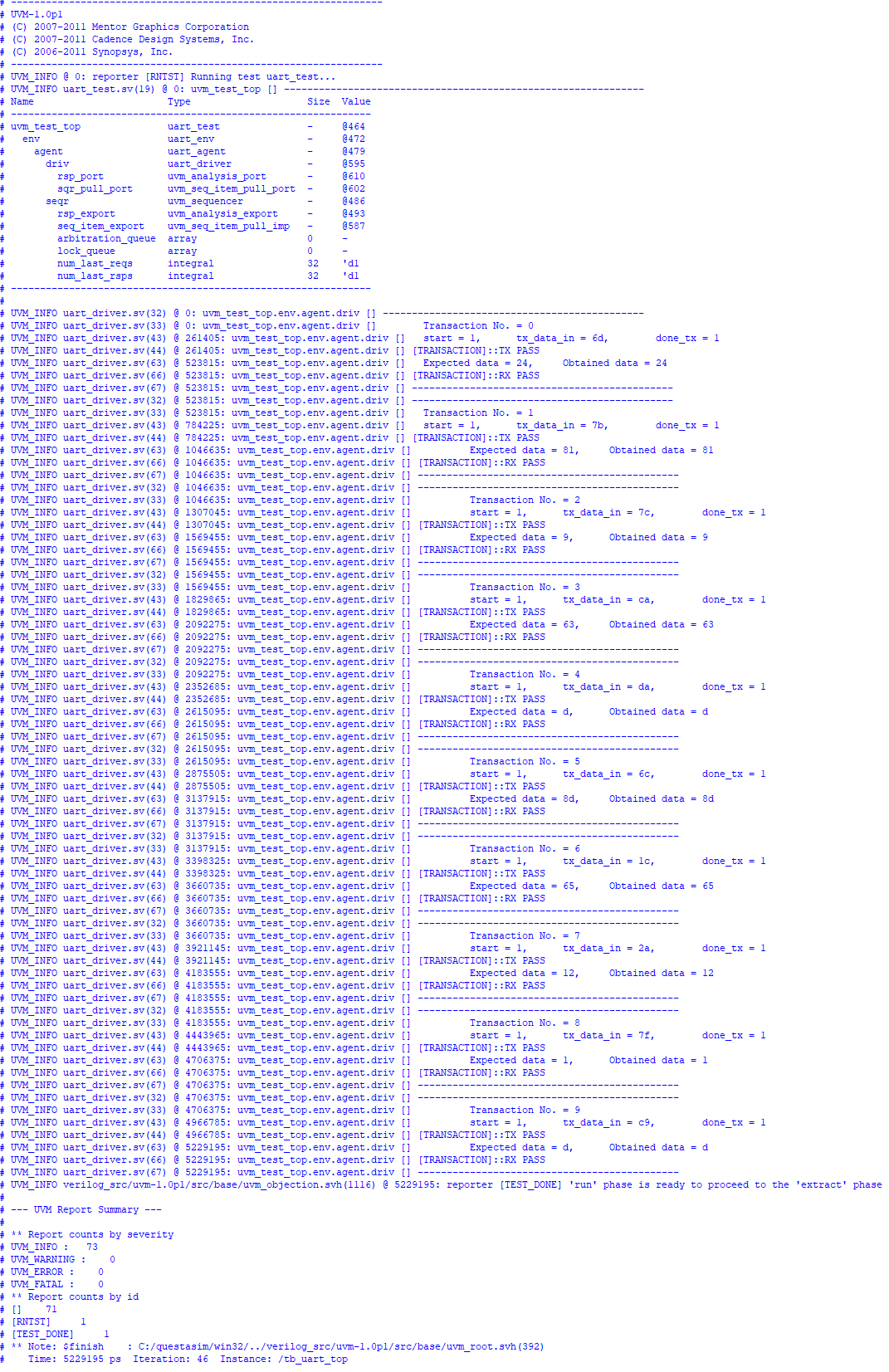
Simulation output:
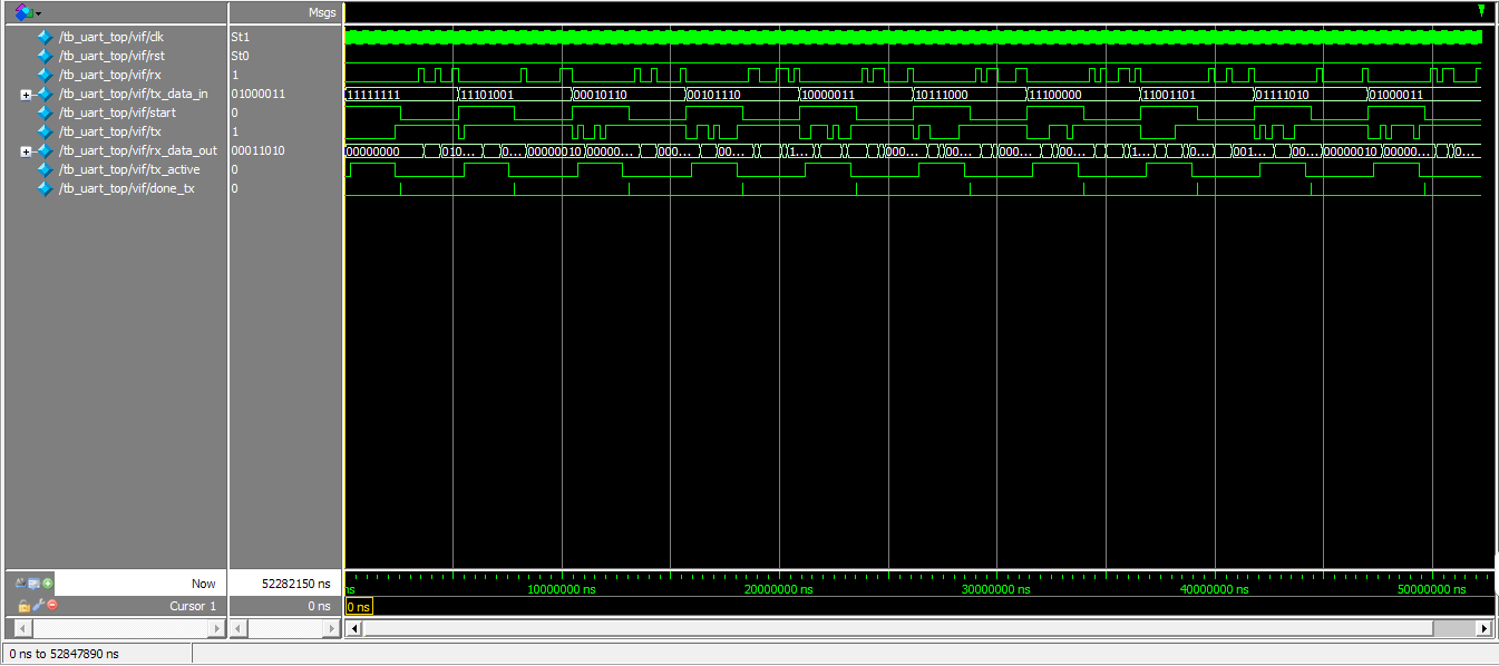
Simulation waveform:
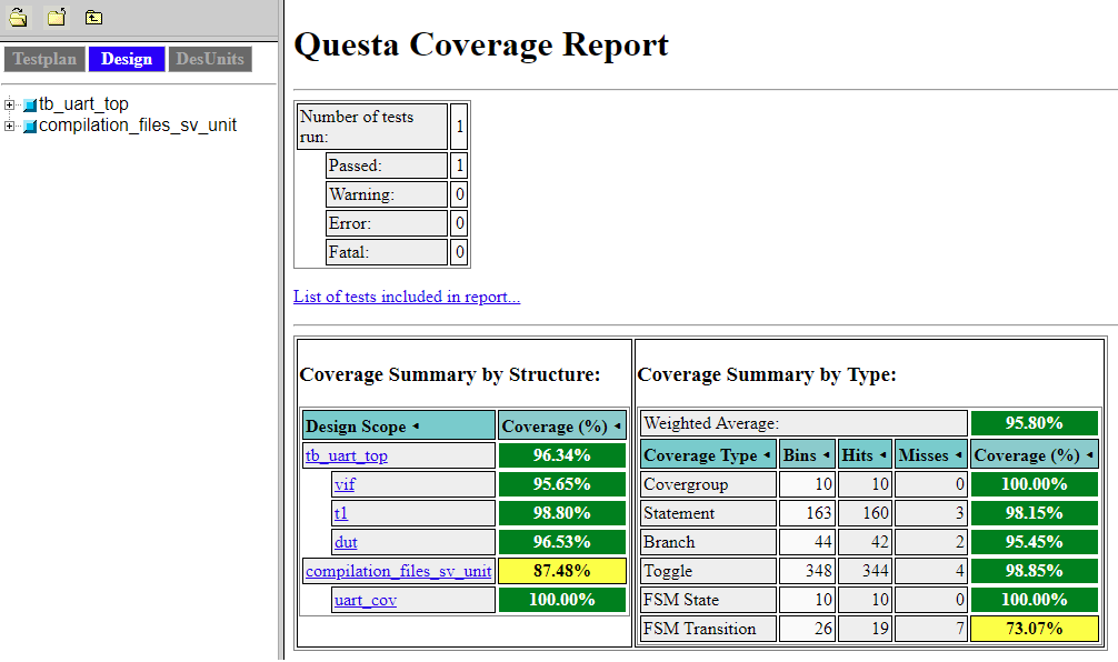
Coverage summary:
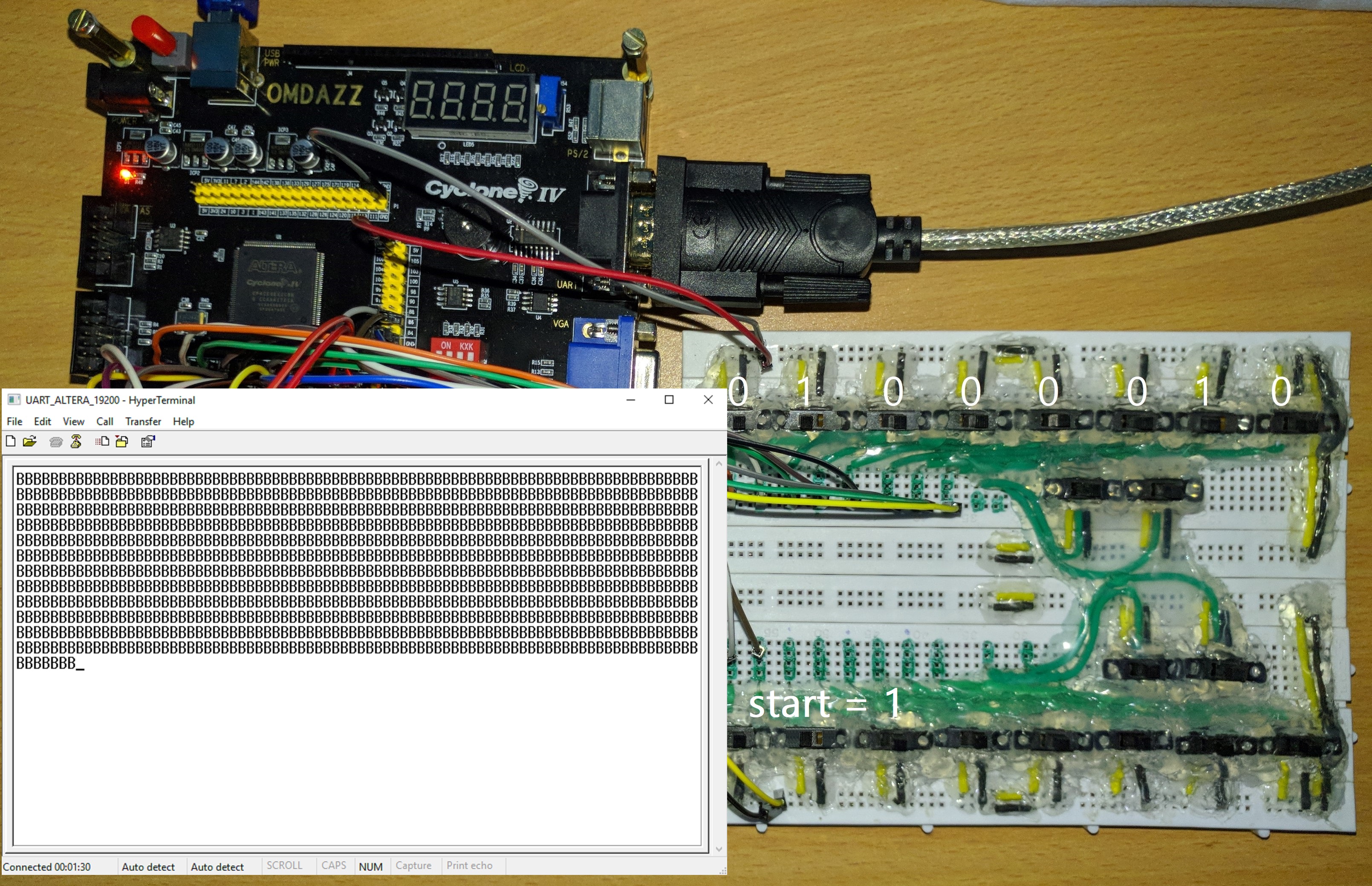
Hardware setup:
On the Hyperterminal software the port settings are made as below.
Bits per second: 19200
Data bits: 8
Partiy bit: None
Stop bits: 1
Flow control: None
RX test: Receving “01100001(a)” from PC using Hyperterminal
TX test: Transmitting “01000010(B)” from FPGA board to PC